Our recent OS release 27 update highlighted a variety of new features, including pin-triggered pulse generator (ptpg). This post will shed light on how ptpg, intended for use with triac circuits, can be utilized to control the brightness of an incandescent bulb.
The ptpg feature lets you set up a one-shot digital output pulse, triggered by another digital input pin. You choose the polarity, input trigger pin, initial delay and on-period when you configure the output:
hardware.pin8.configure(DIGITAL_IN);
hardware.pin5.configure(PTPG_OUT_ACTIVE_HIGH, hardware.pin8, 0.0055, 0.001);
You can then change the delay by simply calling pin.write:
hardware.pin5.write(0.00275);
The ptpg timing resolution is 1us (much faster than can be achieved in Squirrel) and the output pulse length (delay plus on-period) can be up to 65.5ms. Since some rounding may occur, you can read back the actual values with getdelay and getperiod.
server.log(hardware.pin5.getdelay());
server.log(hardware.pin5.getperiod());
As it happens, these timings fit nicely for controlling the gate of a triac in response to a 50/60Hz AC zero crossing detector.
What Do You Need?
If you want to try this yourself, you’ll need the following items:
- An imp (with release 27 or later firmware) and April breakout board
- A USB mini cable (for 5V power)
- A 24V AC-AC adapter (to keep mains electricity at arms length)
- Four 1N4001 diodes (to make a diode bridge)
- Two BC547 NPN transistors
- An MOC3021 non-zero crossing triac opto-coupler
- A 2N6073A triac
- An incandescent bulb and holder (rated 34V peak for 24V RMS)
- Some resistors
Zero Crossing Detector
The first task is to generate a zero crossing signal from the 24V AC, which will be connected to our digital input pin.
One approach is to use a comparator to square off the AC input and produce an edge for each zero crossing event. The ptpg input supports this by triggering on every edge transition it sees.
If you don’t have an op-amp to hand you can make a zero crossing detector from 4 diodes, an NPN transistor and a few resistors:
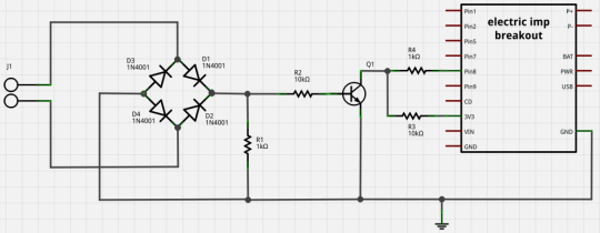
This detector outputs a pulse (not just an edge) for each zero crossing event. The ptpg input supports this too, as long as the detector pulse is shorter than the minimum delay on your output pulse. What’s happening is that ptpg is triggering on the rising edge of the pulse and then re-triggering on the falling edge. Effectively, the output pulse delay starts from the falling edge of the detector.

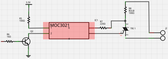
Triac Driver
The next job is to build a circuit to drive the triac gate input, which will switch on your bulb until the next AC zero crossing. It’s essential to isolate your imp pins from AC voltages and switching transients, so I’ve used an MOC3021 opto-coupler. The imp’s ptpg output controls the opto-coupler LED, and a 2N6073A triac is connected to the opto-coupler output (since the integral triac is not designed for switching big loads).
Input Controller and Squirrel Code
Now we need some way to set the brightness of the bulb. I’ve used the Little Devil iOS app, which provides an ideal slider control. The Pitchfork app provides something similar. Either way, you simply configure the app with your agent URL (obtained from the new IDE) and it will send a JSON message to your agent whenever the slider value is changed.
We can use the following snippet of agent code to receive the JSON message and forward it to the device:
http.onrequest(function(req, resp) {
  try {
    resp.send(200, "OK");
    local data = http.jsondecode(req.body);
    if("slider" in data) {
        device.send("brightness", data.slider);
    }
  } catch (ex) {
    resp.send(500, "Internal Server Error: " + ex);
  }
});
Here’s the accompanying device code. Just to be fancy, it ramps the bulb brightness up and down before it receives the first message from the agent:
const upperDelayS = 0.0075;
const lowerDelayS = 0.00275;
const rampPeriodS = 1;
const wakeIntervalS = 0.1;
const onPeriodS = 0.0001;

delayS <- lowerDelayS;
stepS <- (upperDelayS - lowerDelayS) / (rampPeriodS / wakeIntervalS);

triggerPin <- hardware.pin8;
ptpgPin <- hardware.pin5;

triggerPin.configure(DIGITAL_IN);
ptpgPin.configure(PTPG_OUT_ACTIVE_HIGH, triggerPin, delayS, onPeriodS);

agent.on("brightness", function(brightness) {
    stepS = 0;
    delayS = lowerDelayS + (1-brightness.tofloat()) * (upperDelayS-lowerDelayS);
});

function poll() {
    delayS = delayS + stepS;
    if((delayS > upperDelayS) || (delayS < lowerDelayS)) {
        stepS = stepS * -1.0;
    }
    ptpgPin.write(delayS);
    imp.wakeup(wakeIntervalS, poll);
} poll();
Bringing It All Together
Here’s the overall circuit:
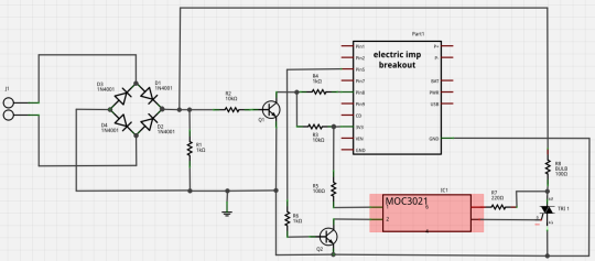
I’m powering the imp from a separate USB cable, with GND tied to the low output of the bridge rectifier. You could regulate 3V3 from the rectified AC instead though. Also worth noting is that if the load you’re switching has significant reactance you will need additional components around the triac to ensure it switches off at each zero crossing. This is described in the data sheet for the opto-coupler.
Hopefully, this provides a good overview of the Imp’s pin-trigger pulse generator and how it can be applied for AC dimming. Of course, it can be used for other fast monostable tasks too.
Phil Michaelson-Yeates
Software Engineer